


 Required
2018-06-27 Update: DIY the SCM system with time setting
Someone are interested in the SCM system recently, I have ever DIY the SCM system with time setting, now I will share it with everyone.Clock module(pic 1)Stc52 microcontroller(pic 2)1602 LCD screen(pic 3)Set interface of date and time.(pic 4)Set the interface of alarm (N is no alarm, alarm setting is Y).(pic 5)Sourcefrom:GeekfansTranslatedby:Utsource
View More >>2018-06-25 Update: DIY a radio in 10 minutes

Step 1: Materials Needed A ferrite loop antenna coil, ferrite magnet can move in and out of the coil for coarse tuning. An adjustable capacitor. One germanium diode. A piezoelectric headset. Two spring clip wire jumpers. 15M long stranded insulated wire as antenna, you can use TV or radio antenna as an alternative. A wooden board or other thing as a base.It is really a simple radio, pls see the pic above. The black wire on the coil is connected to the lead in the middle of the adjustable ca...
View More >>2018-06-15 Update: DIY Wireless Hygrometer
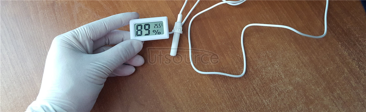
Materials requestedTransmitter: Standard 51 Microcontroller (12mh crystal) x1; 315mhz Transmitter Module x1; Lithium Battery +5v Boost Module x1 (or External Power Supply); 18b20 Digital Temperature Sensor x1; 5x7 Hole Board x1Receiver: ATmega8 microcomputer x1; 315mhz receiver x1; dht11 digital hygrometer x1; Nokia5110 display screen, s8050 transistor x1; 5x7 hole board x1In addition also needswitch, 10k resistor, 10k adjustable resistor, pin, 30p ceramic capacitors, xh2.54 2p carrier, ICcarrie...
View More >>2018-06-14 Update: DIY Eight-channel wireless remote control with AT89C2051

Today, were going to make eight-way wireless remote control by using AT89C2051. I used a pair of 315MHZ receiver for the wireless module. First lets look at the schematic.Receiving part:Transmitting part:The VD8 in the pic is the reset indicating light, it will be on when you press the reset button, which means the the reset button is in good condition, if it is off means the reset button is bad.You must add resistance between p1.0 and p1.1 in AT89C2051, and here is the soldering pic...
View More >>2018-06-13 Update: STC minimum system

In October, I made a stc which can be the smallest systemThis is front side as in the first pic, a few led lights.Soldering according to the circuit diagram. Youd better not use the wire jumper, I couldnt download a microcontroller as I used a wire jumper last time, it almost be destroyed.Source from: GeekfansTranslated by: Utsource
View More >>TAG
DIY utsource 100G QSFP28 SR SR4 10G or 25Gb/s 40G or 100Gb/s Tesla coil 100G QSFP28 SR4 100G QSFP28 LR4 FTTH installation France Version SFP Tx/Rx Motor Active Optical Cable(AOC) 40Gbps 56Gbps QSFP+ AOC Cable SFP+ transceiver SFP10G SR 10G SFP+ SR transceiver Holographic projection Distance sensor CFP CFP optical DIY socket tester Sensor cable 40G QSFP+ Transceiver module CWDM optical transceiver module transceiver AOC cable PAM8403 IC Based Audio NE555 arduino Rain alarm Ultrasonic humidifier Water pump. Solar USB Charger Alarm LED night light Brake Disc Clock DAC Cables Optical

