Endereço de entrega

Olá! Login ou Registre-se agora
APP Manual de dados Transmissão ao vivo 290K likes Utsource

Chips de IC
Circuitos Integrados Digitais da Série 74
Circuitos Integrados Digitais da Série CD40
Acopladores Óticos
ICs de Relógio e Calculadora
Amplificadores Operacionais
Interruptor de Alimentação Ics
Driver Ics
Memória Flash
Memória
Finalidade Especial de Áudio
Relógio/Tempo - Específico da Aplicação
Relógio/Tempo - Buffers de Relógio, Drivers
Relógio/Tempo - Geradores de Relógio, PLLs, Sintetizadores de Frequência
Relógio/Tempo - Linhas de Atraso
Relógio/Tempo - Baterias IC
Relógio/Tempo - Temporizadores e Osciladores Programáveis
Relógio/Tempo - Relógios em Tempo Real
Aquisição de Dados - ADCs/DACs - Finalidade Especial
Aquisição de Dados - Front-end Analógico (AFE)
Aquisição de Dados - Conversores Analógico para Digital (ADC)
Aquisição de Dados - Potenciómetros Digitais
Aquisição de Dados - Conversores Digital para Analógico (DAC)
Aquisição de Dados - Controladores de Ecrã de Toque
Incorporado - CPLDs (Dispositivos Lógicos Programáveis Complexos)
Incorporado - DSP (Processadores de Sinais Digitais)
Incorporado - FPGAs (Matriz de Portas Programável em Campo)
Incorporado - FPGAs (Arranjo de Portas Programável em Campo) com Microcontroladores
Incorporado - Microcontrolador, Microprocessador, Módulos FPGA
Incorporado - Microcontroladores
Incorporado - Microcontroladores - Específico da Aplicação
Incorporado - Microprocessadores
Incorporado - PLDs (Dispositivo Lógico Programável)
Incorporado - Sistema No Chip (SoC)
Interface - Switches Analógicos - Finalidade Especial
Interface - Switches Analógicos, Multiplexadores, Desmultiplexadores
Interface - CODECs
Interface - Controladores
Interface - Síntese Digital Direta (DDS)
Interface - Drivers, Recetores, Transcetores
Interface - Codificadores, Decodificadores, Conversores
Interface - Filtros - Ativo
Interface - Expansores de E/S
Interface - Modems - CIs e Módulos
Interface - Módulos
Interface - Interfaces de Sensores e Detetores
Interface - Sensor, Toque Capacitivo
Interface - Serializadores, Desserializador
Interface - Buffers de Sinal, Repetidores, Divisores
Interface - Terminadores de Sinal
Interface - Especializada
Interface - Telecom
Interface - UARTs (Transmissor Universal de Recetor Assíncrono)
Interface - Gravação e Reprodução de Voz
Linear - Amplificadores - Áudio
Lineares - Amplificadores - Instrumentação, OP Amps, Buffer Amps
Lineares - Amplificadores - Finalidades Especiais
Lineares - Amplificadores - Amplificadores de Vídeo e Módulos
Linear - Multiplicadores Analógicos, Divisores
Linear - Comparadores
Linear - Processamento de Vídeo
Lógica - Buffers, Drivers, Recetores, Transcetores
Lógica - Comparadores
Lógica - Contadores, Divisores
Lógica - Memória FIFOs
Lógica - Flip Flops
Lógica - Portões e Inversores
Lógica - Portões e Inversores - Multifuncional, Configurável
Lógica - Travas
Lógica - Multivibradores
Lógica - Geradores de Paridade e Damas
Logic - Shift Registers
Lógica - Interruptores de Sinal, Multiplexadores, Decodificadores
Lógica - Lógica Especializada
Lógica - Tradutores, Deslocadores de Nível
Lógica - Funções de Barramento Universal
Memória - Baterias
Memória - Proms de Configuração para FPGAs
Memória - Controladores
PMIC - Conversores CA CC, Comutadores Offline
PMIC - Carregadores de Baterias
PMIC - Gestão de Bateria
PMIC - Regulamentação/Gestão Atual
PMIC - Drivers de Vídeo
PMIC - Medição de Energia
PMIC - Drivers Completos, Meia Ponte
PMIC - Gate Drivers
PMIC - Controladores Hot Swap
PMIC - Drivers a Laser
PMIC - Drivers de LED
PMIC - Iluminação, Controladores de Lastro
PMIC - Condutores de Motor, Controladores
PMIC - OU Controladores, Díodos Ideais
PMIC - PFC (Correção do Fator de Potência)
PMIC - Chaves de Distribuição de Energia, Drivers de Carga
PMIC - Gestão de Energia - Especializado
PMIC - Controladores Power Over Ethernet (PoE)
PMIC - Controladores, Monitores de Fontes de Alimentação
PMIC - Conversores RMS para DC
PMIC - Supervisores
PMIC - Gestor Térmico
PMIC - Conversores V/F e F/V
PMIC - Referência de Tensão
PMIC - Reguladores de Tensão - Controladores de Comutação DC DC
PMIC - Reguladores de Tensão - Reguladores de Comutação DC DC
PMIC - Reguladores de Tensão - Linear
PMIC - Reguladores de Tensão - Linear + Comutação
PMIC - Reguladores de Tensão - Controladores Lineares de Reguladores
PMIC - Reguladores de Tensão - Finalidade Especial
CIs Especializados
Módulos
IGBT
IPM
Tirístores
Retificadores
Fonte de Energia
Módulo de Energia Inteligente
SCR, GTO e Díodo
FET
Transístores em Darlington
Módulos de RF
PRODUTOS CNC
CODIFICADOR
Motor
Servo drive e amplificador e Servo
Módulo de Díodo
Módulo Transístor
Relé de Comutação
PLC
Inversor
Contador e Disjuntor
Placa de Elevador
Controlo da Indústria
Transistores
Díodo
Transístores Bipolares
Resistores
Resistores de Filme de Carbono
Resistores de Cimento
Resistores para Montagem de Chassi
Chip Resistor - Montagem em Superfície
Resistores Sensores de Corrente
Resistor de Fusíveis
Resistores de Alta Precisão e Baixo TCR SMD
Resistor de Alta Tensão
Resistores para Fita Led
Resistor MELF
Resistores de Liga de Metal
Resistor de Filme Metálico (TH)
Resistores de Metal Esmaltado
Resistores de Filme de Óxido Metálico
Resistores de Óxido Metálico
Termistores NTC
Termistores PTC
Fotoresistores
Potenciômetros e Resistores Variáveis
Potenciômetro De Precisão
Redes e Matrizes de Resistores
Redes e Matrizes de Resistores (TH)
Resistores Ultra Baixos (SMD)
Resistores Variáveis
Varistores
Resistores de Fio Enrolado
Capacitores
Capacitores Eletrolíticos de Alumínio - SMD
Capacitor CL21
Capacitores de Cerâmica
Capacitores de Alta Tensão
Capacitor de Filme de Poliéster Metalizado
Capacitores de Cerâmica Multicamada MLCC - Com chumbo
Capacitores de Cerâmica Multicamada MLCC - SMD/SMT
Capacitor Mylar
Capacitores de Óxido de Nióbio
Capacitores de Filme de Poliéster
Capacitor Eletrolítico de Polímero Sólido
Supercapacitores e Ultracapacitores
Capacitores de Supressão
Capacitor de Tântalo
Aparadores, Capacitores Variáveis
Indutores e Contas de Ferrite e Transformadores
Antenas
Transformadores de Corrente
Indutores Gerais (TH)
Indutores de Alta Frequência
Indutores (SMD)
Filtro de linha
Indutores de Potência
Transformador de Alimentação
Transformador RJ45
Indutor Radial (TH)
Os Indutores Circulares
Cristais
49S
49SMD
49U
Ressonadores Cerâmicos
Osciladores DIP (XO)
Cristais de Cilindro Radial
Ressonadores SAW
Cristais SMD
Osciladores SMD (XO)
Conectores
Conectores AV
Conectores de Áudio e Vídeo
Conectores Banana e de Ponta de Fio
Conectores de Borda de Cartão
Conectores Circulares
Conector - Soquetes de Cartão
Conectores
Conectores - Acessórios
Conectores - Carcaças
Contatos
Conectores D-Sub
Conectores Ethernet/Conectores Modulares
Conectores FFC, FPC (Flat Flexível)
Conectores de Fibra Óptica
CI e Soquetes de Componentes
Tubos de Luz LED
Conectores Mezzanine (Placa-Placa)
Conectores PCB - Header, Pinos Macho
Conectores PCB - Headers, Receptáculos, Soquetes Fêmea
Conectores PCB - Carcaças
Conectores de Alimentação
Conectores RF/Conectores Coaxiais
Shunts e Jumpers
Blocos Terminais - Acessórios
Blocos de terminais - Blocos Barreira
Blocos Terminais - Trilho Din, Canal
Blocos Terminais- Headers, Plugues e Soquetes
Terminais
Clipes de Teste
Pontos de Teste/Anéis de Teste
Conectores USB
Conectores Não Especificados
Fiação do Tipo Parafuso
Fiação Tipo Mola
Blocos Terminais Plugáveis
Blocos Terminais de Parede
Terminais automotivos
Caixas de terminais, mangas de isolamento e blocos
Conectores e terminais de fio de desconexão rápida
Ferramentas sobressalentes e de desgaste
Conectores automotivos
Conectores de PCB
Transcetores SFP
100BASE SFP
1000BASE SFP
CWDM SFP
DWDM SFP
BIDI SFP
SONET/SDH SFP
2G/4G FC SFP
Customized SFP
SFP+ Transcetores
10G SFP+
BiDi SFP+
CWDM SFP+
DWDM SFP+
8G/16G FC SFP+
Customized SFP+
XFP Transcetores
10G XFP
BIDI XFP
CWDM XFP
DWDM XFP
Customized XFP
Transcetores 40G/100G
40G QSFP+
100G QSFP28
100G CFP
100G CFP2
100G CFP4
Customized 40G/100G
25G SFP28
100G CXP
40G BiDi QSFP+
Cabos óticos ativos
10G SFP+ to SFP+ AOC
40G QSFP+ to QSFP+ AOC
40G QSFP+ to 4xSFP+ AOC
40G QSFP+ to 8xLC AOC
100G QSFP28 AOC
Customized AOC
25G SFP28 AOC
100G QSFP28 to 4xSFP28 AOC
56G QSFP+ to QSFP+
Cabos de conexão direta
10G SFP+ to SFP+ DAC
40G QSFP+ to QSFP+ DAC
40G QSFP+ to 4xSFP+ DAC
25G SFP28 to SFP28 DAC
100G QSFP28 to QSFP28 DAC
100G QSFP28 to 4 SFP28 DAC
Customized DAC
56G QSFP+ to QSFP+
Cabo HDMI de fibra ótica
Optical Fiber Patch Cable
MTP/MPO Plenum Trunks
MTP/MPO-LC Plenum
MTP/MPO LSZH Trunks
MTP/MPO-LC LSZH
OM4 40 100Gb 50/125 Multimode
OM3 10Gb 50/125 Multimode
OM2 50/125 Multimode
OM1 62.5/125 Multimode
OS2 9/125 Singlemode Simplex
OS2 9/125 Singlemode Duplex
OM5 40G 100G 50/125 Multimode
Switchable LC Cables
Uniboot LC Cables
Ultra Low Loss LC SMF
Ultra Low Loss LC MMF
BIF Fiber Cables
Armored Patch Cables
Outros transcetores
Converter Modules
3G/HD-SDI SFP
GBIC Transceivers
PON Transcievers
Transceiver Accessories
Sensores de Temperatura
Interruptor de Controle de Temperatura
Sensor de Temperatura e Humidade
Sensor de Pó
Sensor de PM2.5
Sensor de Gás
Sensor de Gás Combustível
Sensor de Álcool
Sensor de CO
Sensor de Hidrogénio
Sensor de H2S
Sensor de CO2
Ammonia Sensor
Sensor de Formaldeído
Sensor de PIR
Outro Sensor
Sensor de Avaliação Cardíaco
Sensor Ótico
Sensor de Cor
Sensor de Ultrassom
Sensor de Campo Magnético
Sensor de Corrente Elétrica
Sensor de Voltagem
Sensor de Nível Líquido
Sensor de Pressão Atmosférica
Sensor de clima
Sensor de Ângulo de Inclinação
Sensor de Gesto
Sensor de Toque
Sensor de Chamas
Sensor de Vibração
Sensor de Velocidade
Módulos LED
LED de Alta Potência
LED SMD
Retroiluminação LED
LED COB
Display LED
LED de Conexão
Indução de Infravermelhos
LED Piranha
Lâmpadas LED
Diodo Emissor de Luz
Chip Iluminante LED
Placas Epitaxiais Led
LED de Luz Vermelha
LED de Luz de Laranja
LED de Luz Amarela
LED de Luz Verde-Amarela
LED de Luz Verde
LED de Luz Azul
LED de Luz Roxa
LED de luz branca
Outro Chip Iluminante LED
Displays LED

-
0
-
Comprar(0)
-
Inquérito(0)

-


 Required
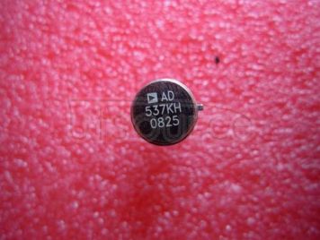
 frequency up to 100 kHz and any F.S. input voltage up to ±30 V. Linearity error is as low as ±0.05% for 10 kHz F.S., and operation is guaranteed over an 80 dB dynamic range. The overall temperature coefficient (excluding the effects of external components) is typically ±30 ppm/°C. The AD537 operates from a single supply of 5 V to 36 V and consumes only 1.2 mA quiescent current.
A temperature-proportional output, scaled to 1.00 mV/K, enables the circuit to be used as a reliable temperature-to-frequency converter<br/> in combination with the fixed reference output of 1.00 V, offset scales such as 0°C or 0°F can be generated.
The low drift (1μV/°C typ) input amplifier allows operation directly from small signals (e.g., thermocouples or strain gages) while offering a high (250 M(Ohm) input resistance. Unlike most V-F converters, the AD537 provides a square-wave output, and can drive up to 12 TTL loads, LEDs, very long cables, etc.
The excellent temperature characteristics and long-term stability of the AD537 are guaranteed by the primary bandgap reference generator and the low T.C. silicon chromium thin film resistors used throughout.
The device is available in either a TO-116 ceramic DIP or a TO-100 metal can<br/> both are hermetically sealed packages.
The AD537 is available in three performance/temperature grades<br/> the J and K grades are specified for operation over the 0°C to +70°C range while the AD537S is specified for operation over the extended temperature range, -55°C to +125°C.")