
PN532 NFC HAT
| ||

Instruction
This is a Raspberry Pi NFC HAT based on PN532 operating in the 13.56MHz frequency range. It supports three communication interfaces: I2C, SPI, and UART.
NFC (Near Field Communication) is a wireless technology that allows contactless point-to-point data communication between devices within a short distance of 10 cm. It is widely used in applications such as access control systems, smart tickets, meal cards, etc.
Based on the popular NFC controller PN532 with multi-interface options, this HAT will easily enable NFC function for your Raspberry Pi.
Features
- Standard Raspberry Pi 40PIN GPIO extension header, supports Raspberry Pi series boards.
- Onboard PN532 chip, supports various NFC/RFID cards like MIFARE/NTAG2xx, etc.
- Three interface options: I2C, SPI, and UART, configured via jumpers and switches.
- Breakout control pins, for easily connecting with host boards like STM32/Arduino.
- Comes with online development resources and manual (examples for Raspberry Python/C, STM32, Arduino).
Specification
- Operating voltage: 3.3V / 5V.
- Factory communication baud rate: 115200 bps.
- Support ISO/IEC 14443A / MIFARE.
- Supports ISO/IEC 14443B in reader mode.
- The NFC module operates in the 13.56 MHz band.
Note
- This module can only be used to write/read an NFC card whose password is known, it cannot be used for decrypting encrypted NFC cards. For example, the default password of all blocks of the Mifare Classic card is 0xFFFFFFFFFFFF. The Mifare card can be written/read-only when the default password isn't changed.
- This module cannot be used to copy a card unless the card uses the default password.
- This module cannot be used to simulate an NFC card. Because the ID of the NFC card is 4 bytes, because of the security policy of PN532, it will set the first byte of the simulated card to 0x08. For more details, please refer to http://www.nfc-tools.org/index.php?title=PN53x%E3%80%82
Quick Testing
You can quickly test the module by connecting it to PC with a USB to TTL module instead of a Raspberry Pi.
- 1. Hardware Connection
| PN532 NFC HAT | USB to TTL Module |
|---|---|
| 3V3 | 3.3V |
| GND | GND |
| TX | RX |
| RX | TX |

- 2. Set L0 to L and L1 to L by jumpers.
- 3. Connect USB to TTL Module to PC by USB cable.
- 4. Open Serial Assistant software and set it.
- Baud rate: 115200
- Data bits: 8
- Stop bits: 1
- Parity: None
- Flow control: None
- 5. Check "HEX" and "HEX".
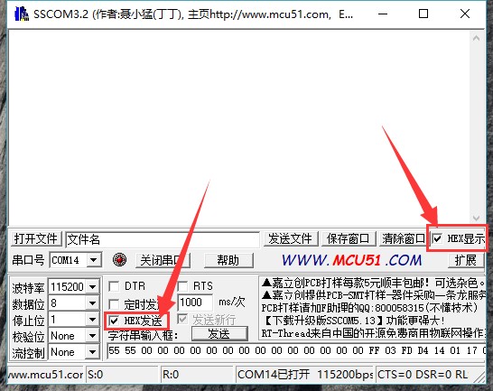

- 6. Select the correct serial port and open it.
- 7. Send the data below to wake up the FN532 module
55 55 00 00 00 00 00 00 00 00 00 00 00 00 00 00 FF 03 FD D4 14 01 17 00
(Please refer to PN532 User Manual HSU wake-up condition Chapter)
The response from the PN532 module should be:
00 00 FF 00 FF 00 00 00 FF 02 FE D5 15 16 00
- 8. Send the data below to scan the Mifare Classic card (The blue card provided, hereafter called "card").
00 00 FF 04 FC D4 4A 01 00 E1 00
Closing card to coil part of the module, module scan it and response:
00 00 FF 0C F4 D5 4B 01 01 00 04 08 04 XXXXXXXXXX 00
XXXXXXXXXX in response data is the ID (3 bytes) and checksum (1 byte) of the card. (Please refer to PN532 User Manual InListPassiveTarget Chapter).
Using demo codes
PN532 NFC HAT supports UART, I2C, and SPI interfaces. You can use them according to your situation. After connecting PN532 NFC HAT (hereafter called PN532) to Raspberry PI, then set the L1, L0 jumpers, and DIP switch for different interfaces.
Choose the interface:
- UART: By default, the UART interface of Raspberry Pi is used for Sheell debugging. If you use the serial port for debugging, you need to add a USB to the TTL module for communicating just like what we do on #Quick testing. In this case, the serial port is mapped as ttyUSB0 instead of ttyS0
- I2C: Raspberry Pi doesn't supports I2C Clock Stretching. However, PN532 may use Clock Stretching (slaver pull-down SCL pin of I2C interface). Clock Stretching causes Raspberry Pi cannot control all I2C devices, therefore, if you need to connect to other i2C devices, we do not recommend you use the I2C interface.
- SPI: We use D4 (BCM) pin as Chip select pin of the SPI interface. Take care of the GPIO conflict.
Raspberry Pi Examples
Download the demo code from #Resources, unzip, and copy the Raspberry Pi folder to /home/pi of Raspberry Pi. You can first copy it to /boot of SD card, then copy it to /home/pi.
sudo apt-get install p7zip-full
wget https://www.waveshare.comhttps://files.waveshare.com/upload/6/67/Pn532-nfc-hat-code.7z
7z x Pn532-nfc-hat-code.7z -r -o./Pn532-nfc-hat-code
sudo chmod 777 -R Pn532-nfc-hat-code/
- SPI Interface
1. Set L0 toL and L1 to H by jumpers.
2. Connect RSTPDN -> D20 by jumper.
3. Set the DIP switch to
| SCK | MISO | MOSI | NSS | SCL | SDA | RX | TX |
| ON | ON | ON | ON | OFF | OFF | OFF | OFF |

4. Connect PN532 NFC HAT to Raspberry Pi.
| PN532 NFC HAT | Raspberry Pi (BCM) |
|---|---|
| SCK | SCK |
| MISO | MISO |
| MOSI | MOSI |
| NSS | P4 (D4) |
5. Enable SPI interface:
Open the Terminal of Raspberry Pi, use the command: sudo raspi-config
Choose Interfacing Options -> SPI -> Yes.
6. Run demo codes (Use example_get_uid.py and rpi_get_uid.c as example).
Open Terminal, and navigate to the directory of demo codes.
cd ~/raspberrypi/
1) python code:
Enter the directory of python codes: cd ~/raspberrypi/python/
Modify example_get_uid.py file, set the initialize code as:
pn532 = PN532_SPI(debug=False, reset=20, cs=4)
#pn532 = PN532_I2C(debug=False, reset=20, req=16)
#pn532 = PN532_UART(debug=False, reset=20)
Save after modifying, then run the codes with the command:
python3 example_get_uid.py
2) C codes:
Enter the directory of the c code: cd ~/raspberrypi/c/example/
Modify rpi_get_uid.c file, set initialize code as:
PN532_SPI_Init(&pn532);
//PN532_I2C_Init(&pn532);
//PN532_UART_Init(&pn532);
Save and compile: sudo make
Run the code:
./rpi_get_uid.exe
7. Expected result: Close the card to the coil part of PN532, and the UID of the card is read.
- UART interface
1. Set L0 to L and L1 to L by jumpers.
2. Connecting RSTPDN -> D20 by jumper.
3. Set the DIP switch to
| SCK | MISO | MOSI | NSS | SCL | SDA | RX | TX |
| OFF | OFF | OFF | OFF | OFF | OFF | ON | ON |

4. Connect PN532 to Raspberry Pi.
| PN532 NFC HAT | Raspberry Pi |
|---|---|
| RX | TX |
| TX | RX |
5. Enable Serial port. By default, the serial port is used for Shell debugging.
Open the Terminal of Raspberry PI and run the command: sudo raspi-config
Choose Interfacing Options -> Serial -> No -> Yes.
【Note】You need to restart Raspberry Pi after enabling the serial port.
6. Run demo codes(Use example_get_uid.py and rpi_get_uid.c as examples)
Open Terminal and navigate to the directory of demo codes:
cd ~/raspberrypi/
1) python code:
Enter the directory of the python code: cd ~/raspberrypi/python/
Modify example_get_uid.py file, set initialize code to:
#pn532 = PN532_SPI(debug=False, reset=20, cs=4)
#pn532 = PN532_I2C(debug=False, reset=20, req=16)
pn532 = PN532_UART(debug=False, reset=20)
Save. Then run the code by command:
python3 example_get_uid.py
2) C code:
Enter the directory of the c code: cd ~/raspberrypi/c/example/
Modify rpi_get_uid.c file, set initialize code to:
//PN532_SPI_Init(&pn532);
//PN532_I2C_Init(&pn532);
PN532_UART_Init(&pn532);
Save then compile code: sudo make
Run code:
./rpi_get_uid.exe
7. Expected result: Close the card to the coil part of PN532, and the UID of the card is read.
- If the demo code of the UART run failed, you can test the serial port by this example
cd ~/raspberrypi/python/
python3 example_uart_hex.py
Enter data and sent, data sent and received should be printed on the terminal as expected. e.g. sent data below to wake up PN532:
55 55 00 00 00 00 00 00 00 00 00 00 00 00 00 00 FF 03 FD D4 14 01 17 00
The response data should be:
00 00 FF 00 FF 00 00 00 FF 02 FE D5 15 16 00
- I2C interface
1. Set L0 as H, L1 as L by jumpers.
2. Connect RSTPDN -> D20 and INT0 -> D16(avoid from Clock Stretching) by jumpers
3. Set the DIP switch to
| SCK | MISO | MOSI | NSS | SCL | SDA | RX | TX |
| OFF | OFF | OFF | OFF | ON | ON | OFF | OFF |

4. Connect PN532 to Raspberry Pi
| PN532 NFC HAT | Raspberry Pi |
|---|---|
| SCL | SCL |
| SDA | SDA |
5. Enable the I2C interface.
Open the Terminal of Raspberry Pi and run the command: sudo raspi-config
Choose Interfacing Options -> I2C -> Yes.
6. Run code (Use example_get_uid.py and rpi_get_uid.c as examples).
Open the terminal and navigate to the directory of demo codes:
cd ~/raspberrypi/
1) python code:
Enter the directory of the python code: cd ~/raspberrypi/python/
Modify example_get_uid.py file, set initialize code to:
#pn532 = PN532_SPI(debug=False, reset=20, cs=4)
pn532 = PN532_I2C(debug=False, reset=20, req=16)
#pn532 = PN532_UART(debug=False, reset=20)
Save, then run the code:
python3 example_get_uid.py
2) C code:
Enter the directory of the c code: cd ~/raspberrypi/c/example/
Modify rpi_get_uid.c file, set initialize code to:
//PN532_SPI_Init(&pn532);
PN532_I2C_Init(&pn532);
//PN532_UART_Init(&pn532);
Save then compile codes: sudo make
Run code:
./rpi_get_uid.exe
7. Expected result: Close the card to the coil part of PN532, and the UID of the card is read.
Arduino Examples
1. Make sure that you have installed Arduino IDE on your PC.
2. Create a new folder in ...\Arduino\libraries (Installation directory of Arduino IDE) and name it as pn532.
3. Copy files pn532.c, pn532.h, pn532_uno.cpp and pn532_uno.h to ...\Arduino\libraries\pn532 from Arduino demo codes.
4. Demo codes are under the examples\arduino (demo codes you download) directory.
5. Herein we take the Arduino UNO board as an example.
- SPI interface
1. Set L0 to L and L1 to H by hy jumpers.
2. Set the DIP switch to:
| SCK | MISO | MOSI | NSS | SCL | SDA | RX | TX |
| ON | ON | ON | ON | OFF | OFF | OFF | OFF |
3. Connect PN532 NFC HAT to Arduino UNO:
| PN532 NFC HAT | Arduino UNO |
|---|---|
| SCK | D13 |
| MISO | D12 |
| MOSI | D11 |
| NSS | D4 |

4. Run codes (Use examples\arduino\uno_get_uid\ uno_get_uid.ino as examples):
Open uno_get_uid.ino file, set initialize code to:
PN532_SPI_Init(&pn532);
//PN532_I2C_Init(&pn532);
Compile and upload codes to Arduino UNO.
Open the Serial Monitor, and press the Reset button of Arduino Uno to reset.
5. Expected result: close the card to the coil part of PN532, and the UID of the card is read and printed.
- I2C interface
1. Set L0 to L and L1 to H by jumpers.
2. Set the DIP switch to
| SCK | MISO | MOSI | NSS | SCL | SDA | RX | TX |
| OFF | OFF | OFF | OFF | ON | ON | OFF | OFF |
3. Connect PN532 NFC HAT to Arduino UNO.
| PN532 NFC HAT | Arduino UNO |
|---|---|
| SCL | A5 |
| SDA | A4 |

4. Run code (Use examples\arduino\uno_get_uid\ uno_get_uid.ino as example):
Open uno_get_uid.ino file, set initialize code to:
//PN532_SPI_Init(&pn532);
PN532_I2C_Init(&pn532);
Compile and upload codes to Arduino UNO board.
Open the Serial monitor, and press the Reset button of the Arduino UNO board to reset.
5. Expected result: close the card to the coil part of PN532, and the UID of the card is read and printed.
STM32 Example
The development board used here is Open103C which is based on STM32F103CBT6.
- Download project
1. Open project by keil software (...\MDK-ARM\pn532_stm32.uvprojx), Click Rebuild to compile the project.
2. Choose programmer: Options for Target -> Debug-> Use, default: ST-Link Debugger.
3. Choose download method: Options for Target -> Debug -> Settings -> Debug -> Port, Default: JTAG.
4. Connect the Open board to the PC by the programmer. Note that you should power the Open board separately.
5. Click Download to download the project.
- Hardware connection
SPI connection
1. Set L0 to L and L1 to H by jumpers.
2. Set the DIP switch to
| SCK | MISO | MOSI | NSS | SCL | SDA | RX | TX |
| ON | ON | ON | ON | OFF | OFF | OFF | OFF |
3. Connect PN632 to Open103C board.
| PN532 NFC HAT | STM32F103CBT6 |
|---|---|
| SCK | PA5 |
| MISO | PA6 |
| MOSI | PA7 |
| NSS | PA4 |
4. Connect the UART1 interface (PA9->RX, PA10->TX) of the STM32 development board to the computer via USB serial cable or serial module.
5. Turn on the serial monitor and press the reset button of the STM32 development board.
6. Expected result: Put the card close to the coil part of the module to get the UID of the card.
Description of examples
Examples above are used to read the UID of the Mifare Classic card (example_get_uid.py / rpi_get_uid.exe / uno_get_uid.ino / stm32_get_uid), here we describe other examples.
【Note】
Before running the examples, you should set the L0/L1 pins and DIp switch according to the interfaces used. You cannot set all the pins to ON, it will cause the data received to be wrong. Here we take 0 is OFF and 1 is ON.
- UART interface: Set jumpers [L1..L0] as LL, set DIP switch to 00000011
- I2C interface: Set jumpers [L1..L0] as LH, set DIP switch to 00001100.
- SPI interface: Set jumpers [L1..L0] as HL, set DIP switch to 11110000.
Read Mifare Classic card
| Examples | Hardware platform |
| example_dump_mifare.py | Raspberry Pi |
| rpi_dump_mifare.c | Raspberry Pi |
| uno_dump_mifare.ino | Arduino UNO |
| stm32_dump_mifare/MDK-ARM/pn532_stm32.uvprojx | STM32F103CBT6 |
Expected result: Close the Mifare Classic card to PN532 NFC HAT, and the data in the card are printed:
0 : 37 F9 20 69 87 08 04 00 62 63 64 65 66 67 68 69
1 : 00 00 00 00 00 00 00 00 00 00 00 00 00 00 00 00
2 : 00 00 00 00 00 00 00 00 00 00 00 00 00 00 00 00
3 : 00 00 00 00 00 00 FF 07 80 69 FF FF FF FF FF FF
4 : 00 00 00 00 00 00 00 00 00 00 00 00 00 00 00 00
5 : 00 00 00 00 00 00 00 00 00 00 00 00 00 00 00 00
6 : 00 00 00 00 00 00 00 00 00 00 00 00 00 00 00 00
7 : 00 00 00 00 00 00 FF 07 80 69 FF FF FF FF FF FF
8 : 00 00 00 00 00 00 00 00 00 00 00 00 00 00 00 00
9 : 00 00 00 00 00 00 00 00 00 00 00 00 00 00 00 00
10 : 00 00 00 00 00 00 00 00 00 00 00 00 00 00 00 00
11 : 00 00 00 00 00 00 FF 07 80 69 FF FF FF FF FF FF
… …
63 : 00 00 00 00 00 00 FF 07 80 69 FF FF FF FF FF FF
Note:
- Data of every row are related to every block of the card
- First 4 bytes of block 0 are the UID of the Mifare Classic card, and the fifth byte is the parity bit. It is the checksum of the first 4 bytes.
- Block 0 (UID) of the classic card cannot be modified.
- Every sector has four blocks, these four blocks use the same password. For example, blocks 4N~4N+3 belong to the same sector.
- Block 4N+3 is cipher block, that is if you want to read the data of blocks 4N~4N+2, you must use cipher of block 4N+3.
- The car has 64 blocks in total, which is 1K.
e.g. To read block 6, we need to use cipher of the related sector, that is the data of block 7.
7: 00 00 00 00 00 00 FF 07 80 69 FF FF FF FF FF FF
The first six bytes are KEY A, it is default FF FF FF FF FF FF, if you read it, the data response would be 00 00 00 00 00 00. The last six bytes are KEY B saved in plaintext. KEY A and KEY B of Mifare Classic card are default FF FF FF FF FF FF.
Four bytes in the middle are Access Bits, default FF 07 80 69. Access Bits are used for controlling access permission, it will be locked if the user writes the wrong data to them .

For example, if you write 0xFF to byte 6, the high four bits of byte 7 should be 0b0000, low four bits of byte 8 should be 0b0000. For more details, please refer to the Access conditions for data blocks section of MF1S50YYX_V1.pdf
The card provided can be unlocked by the "back door" left, however, if you use a common Mifare card, once you write the wrong data to Access Bits, the card will be locked and unable to restore. Be careful when you write card
Read/Write Mifare Classic
| Examples | Hardware Platform |
| example_rw_mifare.py | Raspberry Pi |
| rpi_rw_mifare.c | Raspberry Pi |
| uno_rw_mifare.ino | Arduino UNO |
| stm32_rw_mifare/MDK-ARM/pn532_stm32.uvprojx | STM32F103CBT6 |
Expected result: Close Mifare Classic card to PN532 NFC HAT, block 6 will be written with data 00 01 02 03 04 05 06 07 08 09 0A 0B 0C 0D 0E 0F.
Note:
- Before you write block 6, you should make sure that the cipher of block 6 is 0xFF FF FF FF FF FF, which are the first six bytes of block 7.
- If you want to modify examples and try to write block N+3, you should be careful and remember the cipher. Because that N+3 is cipher block, once you forget the cipher, you should not access block N~N+2 anymore.
Read NTAG2XX card
| Examples | 'Hardware platform |
| example_dump_ntag2.py | Raspberry Pi |
| rpi_dump_ntag2.c | Raspberry Pi |
| uno_dump_ntag2.ino | Arduino UNO |
| stm32_dump_ntag2/MDK-ARM/pn532_stm32.uvprojx | STM32F103CBT6 |
Expected result: Close Ntag215 card to PN532 NFC HAT, data of the card will be printed
0: 04 85 32 3b
1: 92 a8 64 80
2: de 48 00 00
3: e1 10 3e 00
4: 03 00 fe 00
5: 00 00 00 00
6: 00 00 00 00
7: 00 00 00 00
… …
134: 00 00 00 00
Note:
- Ntag215 card should be purchased separately.
- Page of Ntag215 card just like blocks of Mifare card.
- The first three bytes of page 0 is UID0~UID2 of Ntag215 card, the fourth byte is parity bits, it is the checksum of the first three bytes and 0x88 (Cascade Tag).
- Page 1 are UID3 ~ UID6 of card.
- The first byte of Page 2 is the parity bit, it is the checksum (Xor) of UID3 ~ UOD6.
Read/Write NTAG2XX Card
| Examples | Hardware platform |
| example_rw_ntag2.py | Raspberry Pi |
| rpi_rw_ntag2.c | Raspberry Pi |
| uno_rw_ntag2.ino | Arduino UNO |
| stm32_rw_ntag2/MDK-ARM/pn532_stm32.uvprojx | STM32F103CBT6 |
Expected result: Close Ntag215 card to PN532 NFC HAT, data 00 01 02 03 are written to Page 6.
Note:
- The last two bytes of Page 2 are used for flagging and locking the page from 03h to 0Fh, setting them to read-only mode. This operation is not reversible. Please take care of it when you try to write the page. For more details, please refer to the Static lock bytes (NTAG21x) Section of the NTAG213/215/216 file.

- If you want to lock data of pages after Page 10h, you should write corresponding addresses to the first three bytes of Page 28h (Ntag213), Page 82h (Ntag215), or Page E2h (Ntag216). For details, please refer to the Dynamic Lock Bytes Section of NTAG213/215/216 file.

- About more functions of Ntag2xx car please refer to NTAG213/215/216 manual.
Write GPIO of PN532
| Examples | Hardware platform |
| example_write_gpio.py | Raspberry Pi |
| rpi_write_gpio.c | Raspberry Pi |
| uno_write_gpio.ino | Arduino UNO |
| stm32_write_gpio/MDK-ARM/pn532_stm32.uvprojx | STM32F103CBT6 |
Expected result: Print status of PN532's GPIO.
Pin P30: 1
Pin P31: 0
Pin P32: 1
Pin P33: 0
Pin P34: 1
Pin P35: 0
Pin P71: 0
Pin P72: 1
Pin I0: 1
Pin I1: 0
Note:
Examples will set GPIO:P30 -> HIHG, P31 -> LOW, P33 -> LOW, P35 -> LOW, P71 -> LOW, P72 -> HIGH.
Note:
- P32 is int0, once it is set to LOW, PN532 is reset.
- P34 is SIC_CLK, it is always High when you read it.
- P71 is MISO, it is High when you set PN532 to SPI mode.
- P72 is SCK, it is High when you set PN532 to SPI Mode.
- When powering, PN532 will set communication mode according to L0/L1. After setting, you can remove jumpers and use them as GPIO.
The states of PIN P30 -- P35 will be set to High after hardware reset (RSTPDN is set to Low for 2s and then set to High).
Read GPIO of PN532
| Examples | Hardware Platform |
| example_read_gpio.py | Raspberry Pi |
| rpi_read_gpio.c | Raspberry Pi |
| uno_read_gpio.ino | Arduino UNO |
| stm32_read_gpio/MDK-ARM/pn532_stm32.uvprojx | STM32F103CBT6 |
Expected result: Print states of PN532's GPIO.
Port P3: 0x3f
Port P7: 0x07
Port I: 0x07
Pin P30: 1
Pin P31: 1
Pin P32: 1
Pin P33: 1
Pin P34: 1
Pin P35: 1
Pin I0: 1
Pin I1: 0
Note:
The states of PIN P30 -- P35 will be set to High after hardware reset (RSTPDN is set to Low for 2s and then set to High).
Resources
Documents
- PN532DS User Manual
- PN532UM User Manual
- NTAG213_215_216 User Manual
- MF1S50YYX_V1 Datasheet
- NFC-tools Reference Manual
- PN532 NFC HAT 3D Drawing
Demo codes
FAQ
The NFC card can be formatted using the following procedure:
wget https://files.waveshare.com/upload/8/85/Pn532test.zip
unzip Pn532test.zip
cd pn532test/
sudo sh install.sh
sudo python3 test.py
{{{5}}}
Support
Technical Support
If you need technical support or have any feedback/review, please click the Submit Now button to submit a ticket, Our support team will check and reply to you within 1 to 2 working days. Please be patient as we make every effort to help you to resolve the issue.
Working Time: 9 AM - 6 AM GMT+8 (Monday to Friday)