

IC Chips
74 series Digital Integrated Circuits
CD40 series Digital Integrated Circuits
Optical Couplers
Clock & Calculator ICs
Operational Amplifiers
Power Switch Ics
Driver Ics
Flash Memory
Memory
Audio Special Purpose
Clock/Timing - Application Specific
Clock/Timing - Clock Buffers, Drivers
Clock/Timing - Clock Generators, PLLs, Frequency Synthesizers
Clock/Timing - Delay Lines
Clock/Timing - IC Batteries
Clock/Timing - Programmable Timers and Oscillators
Clock/Timing - Real Time Clocks
Data Acquisition - ADCs/DACs - Special Purpose
Data Acquisition - Analog Front End (AFE)
Data Acquisition - Analog to Digital Converters (ADC)
Data Acquisition - Digital Potentiometers
Data Acquisition - Digital to Analog Converters (DAC)
Data Acquisition - Touch Screen Controllers
Embedded - CPLDs (Complex Programmable Logic Devices)
Embedded - DSP (Digital Signal Processors)
Embedded - FPGAs (Field Programmable Gate Array)
Embedded - FPGAs (Field Programmable Gate Array) with Microcontrollers
Embedded - Microcontroller, Microprocessor, FPGA Modules
Embedded - Microcontrollers
Embedded - Microcontrollers - Application Specific
Embedded - Microprocessors
Embedded - PLDs (Programmable Logic Device)
Embedded - System On Chip (SoC)
Interface - Analog Switches - Special Purpose
Interface - Analog Switches, Multiplexers, Demultiplexers
Interface - CODECs
Interface - Controllers
Interface - Direct Digital Synthesis (DDS)
Interface - Drivers, Receivers, Transceivers
Interface - Encoders, Decoders, Converters
Interface - Filters - Active
Interface - I/O Expanders
Interface - Modems - ICs and Modules
Interface - Modules
Interface - Sensor and Detector Interfaces
Interface - Sensor, Capacitive Touch
Interface - Serializers, Deserializers
Interface - Signal Buffers, Repeaters, Splitters
Interface - Signal Terminators
Interface - Specialized
Interface - Telecom
Interface - UARTs (Universal Asynchronous Receiver Transmitter)
Interface - Voice Record and Playback
Linear - Amplifiers - Audio
Linear - Amplifiers - Instrumentation, OP Amps, Buffer Amps
Linear - Amplifiers - Special Purpose
Linear - Amplifiers - Video Amps and Modules
Linear - Analog Multipliers, Dividers
Linear - Comparators
Linear - Video Processing
Logic - Buffers, Drivers, Receivers, Transceivers
Logic - Comparators
Logic - Counters, Dividers
Logic - FIFOs Memory
Logic - Flip Flops
Logic - Gates and Inverters
Logic - Gates and Inverters - Multi-Function, Configurable
Logic - Latches
Logic - Multivibrators
Logic - Parity Generators and Checkers
Logic - Shift Registers
Logic - Signal Switches, Multiplexers, Decoders
Logic - Specialty Logic
Logic - Translators, Level Shifters
Logic - Universal Bus Functions
Memory - Batteries
Memory - Configuration Proms for FPGAs
Memory - Controllers
PMIC - AC DC Converters, Offline Switchers
PMIC - Battery Chargers
PMIC - Battery Management
PMIC - Current Regulation/Management
PMIC - Display Drivers
PMIC - Energy Metering
PMIC - Full, Half-Bridge Drivers
PMIC - Gate Drivers
PMIC - Hot Swap Controllers
PMIC - Laser Drivers
PMIC - LED Drivers
PMIC - Lighting, Ballast Controllers
PMIC - Motor Drivers, Controllers
PMIC - OR Controllers, Ideal Diodes
PMIC - PFC (Power Factor Correction)
PMIC - Power Distribution Switches, Load Drivers
PMIC - Power Management - Specialized
PMIC - Power Over Ethernet (PoE) Controllers
PMIC - Power Supply Controllers, Monitors
PMIC - RMS to DC Converters
PMIC - Supervisors
PMIC - Thermal Management
PMIC - V/F and F/V Converters
PMIC - Voltage Reference
PMIC - Voltage Regulators - DC DC Switching Controllers
PMIC - Voltage Regulators - DC DC Switching Regulators
PMIC - Voltage Regulators - Linear
PMIC - Voltage Regulators - Linear + Switching
PMIC - Voltage Regulators - Linear Regulator Controllers
PMIC - Voltage Regulators - Special Purpose
Specialized ICs
Modules
IGBT
IPM
Thyristors
Rectifiers
Power Supply
Smart Power Module
SCR,GTO and Diode
FET
Darlington Transistors
RF Modules
CNC PRODUCTS
ENCODER
Motor
Servo drive & amplifier & Servo
Diode Module
Transistor Module
Switch Relay
PLC
Inverter
Contactor & Breaker
Elevator Board
Industry Control
Transistors
Diodes
Bipolar transistors
Resistors
Carbon Film Resistors
Cement Resistors
Chassis Mount Resistors
Chip Resistor - Surface Mount
Current Sense Resistors
Fusible Chip Resistor
High Precision & Low TCR SMD Resistors
High Voltage Resistor
LED Strip Resistors
MELF Resistor
Metal Alloy Resistors
Metal Film Resistor (TH)
Metal Glaze Resistors
Metal Oxide Film Resistors
Metal Oxide Resistors
NTC Thermistors
PTC Thermistors
Photoresistors
Potentiometers & Variable Resistors
Precision Potentiometer
Resistor Networks & Arrays
Resistor Networks & Arrays (TH)
Ultra Low Resistors (SMD)
Variable Resistors
Varistors
Wirewound Resistors
Capacitors
Aluminum Electrolytic Capacitors - SMD
CL21 Capacitor
Ceramic Disc Capacitors
High Voltage Capacitors
Metallized Polyester Film Capacitor
Multilayer Ceramic Capacitors MLCC - Leaded
Multilayer Ceramic Capacitors MLCC - SMD/SMT
Mylar Capacitor
Niobium Oxide Capacitors
Polyester Film Capacitors
Solid Polymer Electrolytic Capacitor
Supercapacitors & Ultracapacitors
Suppression Capacitors
Tantalum Capacitors
Trimmers, Variable Capacitors
Inductors & Ferrite Beads & Transformers
Antennas
Current Transformers
General Inductors (TH)
HF Inductors
Inductors (SMD)
LINE Filter
Power Inductors
Power Transformer
RJ45 Transformer
Radial Inductor (TH)
The circular inductors
Crystals
49S
49SMD
49U
Ceramic Resonators
DIP Oscillators(XO)
Radial Cylinder Crystals
SAW Resonators
SMD Crystals
SMD Oscillators(XO)
Connectors
AV Connectors
Audio & Video Connectors
Banana and Tip Connectors
Card Edge Connectors
Circular Connectors
Connector - Card Sockets
Connectors
Connectors - Accessories
Connectors - Housings
Contacts
D-Sub Connectors
Ethernet Connectors/Modular Connectors
FFC, FPC (Flat Flexible) Connectors
Fiber Optic Connectors
IC & Component Sockets
LED Light Pipes
Mezzanine Connectors (Board to Board)
PCB Connectors - Headers, Male Pins
PCB Connectors - Headers, Receptacles, Female Sockets
PCB Connectors - Housings
Power Connectors
RF Connectors/Coaxial Connectors
Shunts & Jumpers
Terminal Blocks - Accessories
Terminal Blocks - Barrier Blocks
Terminal Blocks - Din Rail, Channel
Terminal Blocks - Headers, Plugs and Sockets
Terminals
Test Clips
Test Points/Test Rings
USB Connectors
Unspecified Connectors
Screw-type wiring
Spring-type wiring
Pluggable Terminal Blocks
Through-wall Terminal Blocks
Automotive Terminals
Terminal Housings, Insulation Sleeves & Blocks
Quick Disconnect Wire Connectors and Terminals
Spare & Wear Tooling
Automotive Connectors
PCB Connectors
SFP Transceivers
100BASE SFP
1000BASE SFP
CWDM SFP
DWDM SFP
BIDI SFP
SONET/SDH SFP
2G/4G FC SFP
Customized SFP
SFP+ Transceivers
10G SFP+
BiDi SFP+
CWDM SFP+
DWDM SFP+
8G/16G FC SFP+
Customized SFP+
XFP Transceivers
10G XFP
BIDI XFP
CWDM XFP
DWDM XFP
Customized XFP
40G/100G Transceivers
40G QSFP+
100G QSFP28
100G CFP
100G CFP2
100G CFP4
25G SFP28
100G CXP
Customized 40G/100G
40G BiDi QSFP+
Active Optical Cables
10G SFP+ to SFP+ AOC
40G QSFP+ to QSFP+ AOC
40G QSFP+ to 4xSFP+ AOC
40G QSFP+ to 8xLC AOC
100G QSFP28 AOC
Customized AOC
25G SFP28 AOC
100G QSFP28 to 4xSFP28 AOC
56G QSFP+ to QSFP+
Direct Attach Cables
10G SFP+ to SFP+ DAC
40G QSFP+ to QSFP+ DAC
40G QSFP+ to 4xSFP+ DAC
25G SFP28 to SFP28 DAC
100G QSFP28 to QSFP28 DAC
100G QSFP28 to 4 SFP28 DAC
Customized DAC
56G QSFP+ to QSFP+
Fiber optic HDMI cable
Optical Fiber Patch Cable
MTP/MPO Plenum Trunks
MTP/MPO-LC Plenum
MTP/MPO LSZH Trunks
MTP/MPO-LC LSZH
OM4 40 100Gb 50/125 Multimode
OM3 10Gb 50/125 Multimode
OM2 50/125 Multimode
OM1 62.5/125 Multimode
OS2 9/125 Singlemode Simplex
OS2 9/125 Singlemode Duplex
OM5 40G 100G 50/125 Multimode
Switchable LC Cables
Uniboot LC Cables
Ultra Low Loss LC SMF
Ultra Low Loss LC MMF
BIF Fiber Cables
Armored Patch Cables
Other Transceivers
Converter Modules
3G/HD-SDI SFP
GBIC Transceivers
PON Transcievers
Transceiver Accessories
Temperature Sensors
Temperature Control Switch
Temperature and Humidity Sensor
Dust Sensor
PM2.5 Sensor
Gas Sensor
Combustible Gas Sensor
Alcohol Sensor
CO Sensor
Hydrogen Sensor
H2S Sensor
CO2 Sensor
Ammonia Sensor
Formaldehyde Sensor
PIR Sensor
Flow Sensors
Pressure Sensors
Other Sensor
Heart Rate Sensor
Optical Sensor
Color Sensor
Ultrasound Sensor
Magnetic Field Sensor
Electric Current Sensor
Voltage Sensor
Liquid Level Sensor
Atmospheric Pressure Sensor
Weather Sensor
Tilt Angle Sensor
Gesture Sensor
Touch Sensor
Flame Senor
Vibration Sensor
Speed Sensor
LED modules
High-Power LED
SMD LED
LED backlight
COB LED
LED Display
Plug In LED
Infrared Induction
Piranha LED
LED Bulbs
Light Emitting Diode
LED Illuminant Chip
Led Epitaxial Wafers
Red-Light LED
Orange-Light LED
Yellow-Light LED
Green-Yellow Light LED
Green-Light LED
Blue-Light LED
Purple-Light LED
White-Light LED
Other LED Illuminant Chip
LED Displays

-
0
-
Buy(0)
-
Inquiry(0)

-


 Required
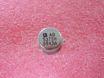
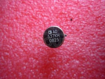
 frequency up to 100 kHz and any F.S. input voltage up to ±30 V. Linearity error is as low as ±0.05% for 10 kHz F.S., and operation is guaranteed over an 80 dB dynamic range. The overall temperature coefficient (excluding the effects of external components) is typically ±30 ppm/°C. The AD537 operates from a single supply of 5 V to 36 V and consumes only 1.2 mA quiescent current.
A temperature-proportional output, scaled to 1.00 mV/K, enables the circuit to be used as a reliable temperature-to-frequency converter<br/> in combination with the fixed reference output of 1.00 V, offset scales such as 0°C or 0°F can be generated.
The low drift (1μV/°C typ) input amplifier allows operation directly from small signals (e.g., thermocouples or strain gages) while offering a high (250 M(Ohm) input resistance. Unlike most V-F converters, the AD537 provides a square-wave output, and can drive up to 12 TTL loads, LEDs, very long cables, etc.
The excellent temperature characteristics and long-term stability of the AD537 are guaranteed by the primary bandgap reference generator and the low T.C. silicon chromium thin film resistors used throughout.
The device is available in either a TO-116 ceramic DIP or a TO-100 metal can<br/> both are hermetically sealed packages.
The AD537 is available in three performance/temperature grades<br/> the J and K grades are specified for operation over the 0°C to +70°C range while the AD537S is specified for operation over the extended temperature range, -55°C to +125°C.")