


 Required
≥{{item.MinNumber}}:
{{pro.LadderPrices[num].viewPrice}}
{{item.viewPrice}}
Click Here to enter Utsource site
Hello! Sign In or Register now
APP Datasheet 380K likes Utsource 1 Million+ Like Utsource
Buy(0)
Inquiry(0)


Dear customers, due to the implementation of the GDPR policy in Europe, UTSOURCE has also made adjustment accordingly to meet the policy requirements. Please read the new privacy policy carefully and this window will no longer pop up after you accept it.
Delivery Address

+ Add Address
The new shipping address
* Please fill in the cell phone number correctly to make sure that you can receive the tracking info in time.
Country Code


Favorite
Utsource certified original
Utsource certified original parts provide the following guarantees:
1. Utsource guarantees 100% original.
2. Utsource certified original parts can be returned and refunded unconditionally within 90 days.
Description
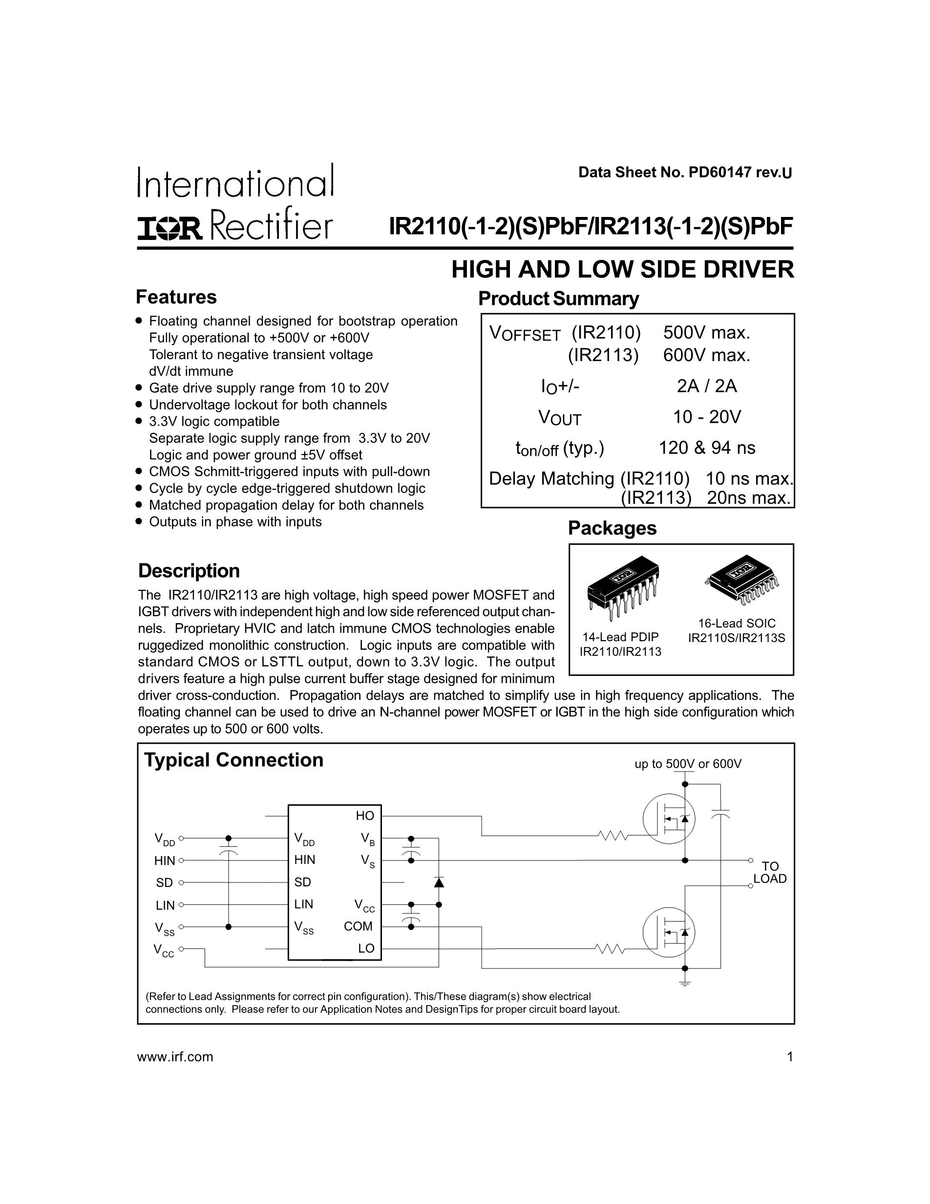
HIGH AND LOW SIDE DRIVER
All product names, trademarks, brands and logos used on this site are the property of their respective owners. The depiction, description or sale of products featuring these names, trademarks, brands and logos is for identification purposes only and is not intended to indicate any affiliation with or authorization by any rights holder.
| Parameter | Symbol | Min | Typical | Max | Unit | Notes |
|---|---|---|---|---|---|---|
| Supply Voltage (High Side) | VB | 10 | - | 20 | V | High-side supply voltage |
| Supply Voltage (Low Side) | VSS | 0 | - | 18 | V | Low-side supply voltage |
| Logic Input Voltage (High) | VIH | 2 | - | 20 | V | Logic input high voltage |
| Logic Input Voltage (Low) | VIL | 0 | - | 0.8 | V | Logic input low voltage |
| Output Current (Source) | IOH | - | 1.5 | - | A | Output current when sourcing |
| Output Current (Sink) | IOL | - | 1.5 | - | A | Output current when sinking |
| Gate Drive Voltage | VGS | 4 | - | 20 | V | Gate drive output voltage |
| Gate Drive Resistance | RDS(on) | - | 1.5 | - | Ω | On-state resistance of the gate driver |
| Propagation Delay Time | td | 35 | 50 | 75 | ns | Propagation delay time |
| Rise Time | tr | 15 | 25 | 40 | ns | Rise time of the output signal |
| Fall Time | tf | 15 | 25 | 40 | ns | Fall time of the output signal |
| Operating Temperature Range | TA | -40 | - | 125 | °C | Ambient operating temperature range |
| Storage Temperature Range | TSTG | -65 | - | 150 | °C | Storage temperature range |
Power Supply:
Logic Inputs:
Gate Drive:
Output Current:
Timing Parameters:
Temperature:
Protection:
Layout Considerations:
By following these instructions, you can ensure optimal performance and reliability of the IR2110 in your application.
(For reference only)The IR2110/IR2113 are high voltage, high speed power MOSFET and IGBT drivers with independent high and low side referenced output channels. Proprietary HVIC and latch immune CMOS technologies enable ruggedized monolithic construction. Logic inputs are compatible with
standard CMOS or LSTTL output, down to 3.3V logic. The output drivers feature a high pulse current buffer stage designed for minimum driver cross-conduction. Propagation delays are matched to simplify use in high frequency applications. The floating channel can be used to drive an N-channel power MOSFET or IGBT in the high side configuration which operates up to 500 or 600 volts.
Features
● Floating channel designed for bootstrap operation Fully operational to +500V or +600V Tolerant to negative transient
voltage dV/dt immune
● Gate drive supply range from 10 to 20V
● Undervoltage lockout for both channels
● 3.3V logic compatible Separate logic supply range from 3.3V to 20V Logic and power ground ±5V offset
● CMOS Schmitt-triggered inputs with pull-down
● Cycle by cycle edge-triggered shutdown logic
● Matched propagation delay for both channels
● Outputs in phase with inputs
What is IR2110
IR2110 is a MOSFET gate driver IC that can used to drive high and low side configurations. Usually to drive two MOSFETs in half bridge or high and low side configuration we will need complicated driver circuit with complementary transistors dual voltage supplies and lots of other complementary devices such as resistors, capacitors and diodes. However, we can achieve the same function using IR2110 MOSFET driver IC only using few other complementary components. You can see the physical appearance of the IR2110 MOSFET driver IC in below image.
Pinout of IR2110:
IR2110 MOSFET driver IC comes in a 14 pin DIP package and a 16 pin SOIC package. In below image pinout of the 14 pin DIP packaged IR2110 IC is given.
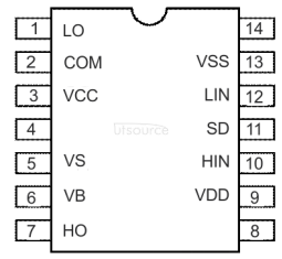
Figure 3. – Pinout of IR2110
Lets identify the pin functions and more details on each pin of IR2110
· Pin 1 – LO – Low side MOSFET gate output pin
· Pin 2 – COM – Low side return pin or the MOSFET common pin.
· Pin 3 – VCC– Voltage supply for the gate voltage.
· Pin 4 – NC – Not connected
· Pin 5 – VS – High side floating voltage supply return pin
· Pin 6 – VB – High side floating voltage supply pin
· Pin 7 – HO – High side MOSFET gate output pin
· Pin 8 – NC – Not connected
· Pin 9 – VDD – IC control power input
· Pin 10 – HIN – High side driving signal input
· Pin 11 – SD – IC shutdown input
· Pin 12 – LIN – Low side input signal
· Pin 13 – VSS – Ground connection
· Pin 14 – NC – Not connected
Features of S202S02:
Lets identify the key features of the IR2110 MOSFET driver IC
· Up to 600V driving voltage
· 10V to 20V gate drive capabilities
· 3.3V minimum logic supply voltage.
Basic Circuit Diagram:
Given below is the basic circuit diagram of the DIY cooler/ Heater circuit.
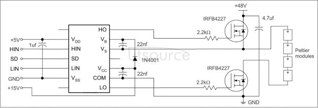
Figure 4. – DIY cooler / Heater
Key Components :
We will need fallowing components other than our key components. Each and every component is given below in the list
1. IRFB4227 MOSFET
2. IR2110 MOSFET Driver
3. 1N4001 diode
4. 2.2kΩ resistor
5. 0.22nF capacitor
6. 4.7uF 100V capacitor
7. 1uF capacitor
Tools Needed:
1. Soldering Iron
2. Iron Stand
3. Flux
4. Nose pliers
Step By Step Guide:
Step 1: Arrange above given components.
Step 2: Solder or connect all the components as shown in the circuit diagram.
Step 3: Supply all three supply voltages. You adjust the 5V and 48V as per your requirement
Step 4: Connect a pwm controller or an Arduino to the signal inputs.
How It Works:
When the control signals are provided IR2110 will drive the two MOSFETs according to the signal you can change the polarity and change the effect to cooling or the heating.
Conclusion:
This can be used as a room cooler or heater with proper insulation. And this also can be used as a CPU cooler pith proper setup with fans.
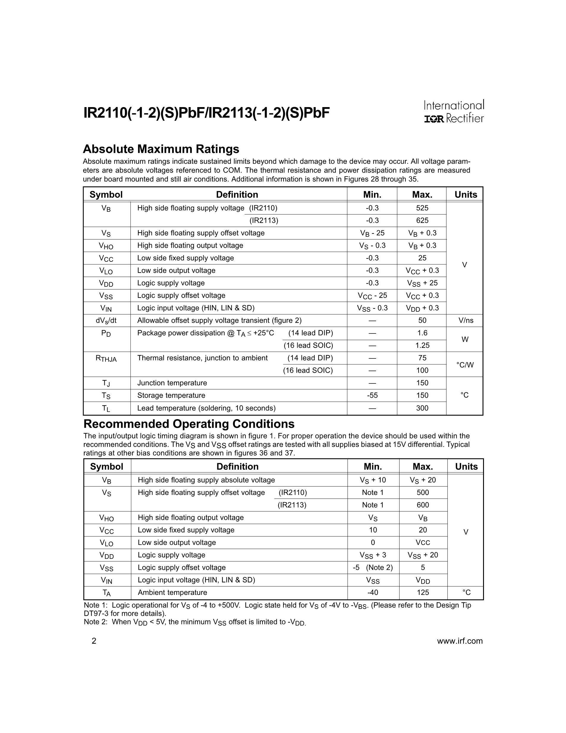
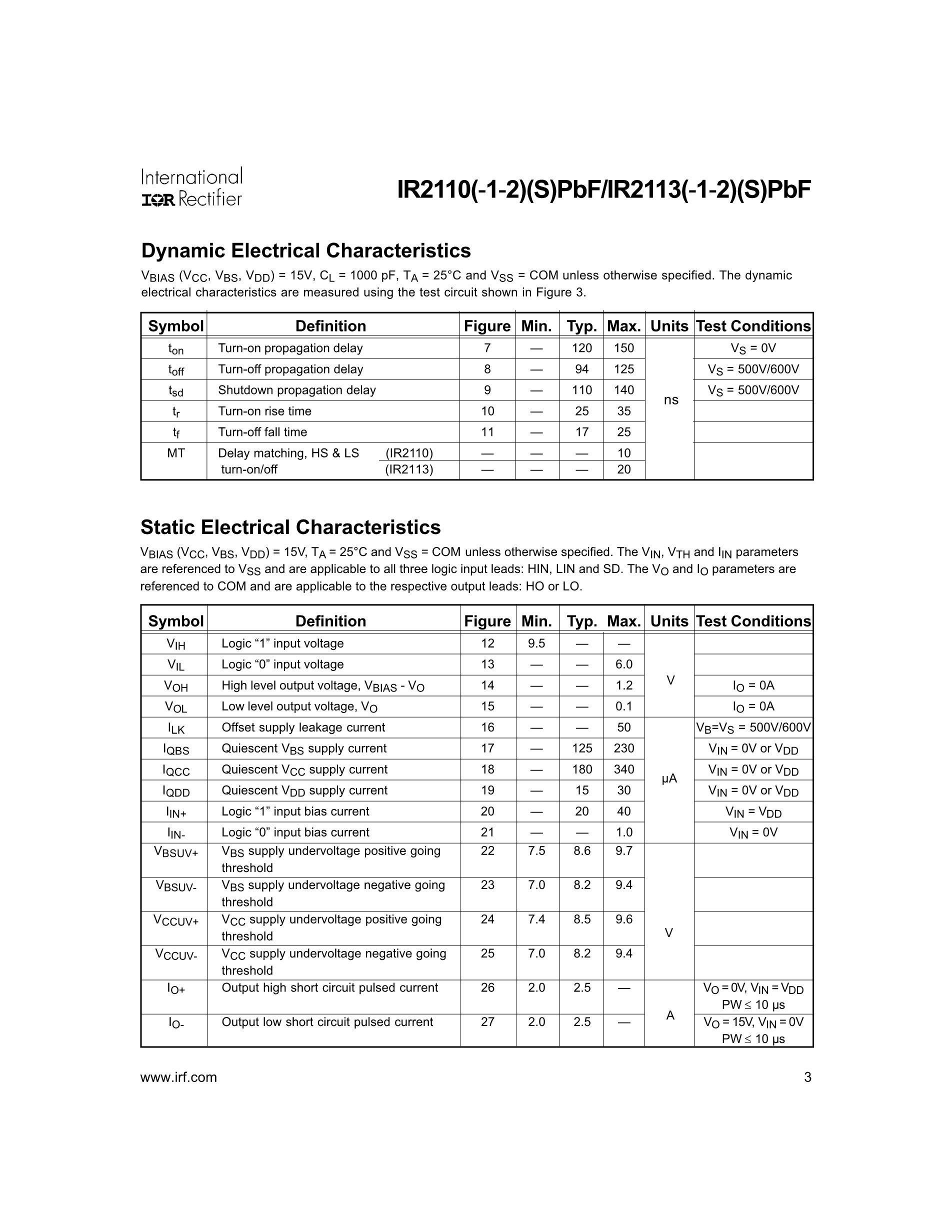
Preview of the first 3 pages of the data sheet
| QUANTITY | UNIT PRICE | PLUS UNIT PRICE | TOTAL PRICE |
|---|---|---|---|
| ≥1: | US $2.50380 | US $2.25342 | US $2.25342 |
| ≥5: | US $1.66920 | US $1.50228 | US $7.51140 |
| ≥10: | US $1.50228 | US $1.35205 | US $13.52050 |
| ≥20: | US $1.46055 | US $1.31450 | US $26.29000 |
| ≥50: | US $1.41882 | US $1.27694 | US $63.84700 |
| ≥100: | US $1.37709 | US $1.23938 | US $123.93800 |
| ≥200: | US $1.33536 | US $1.20182 | US $240.36400 |
| ≥500: | US $1.31867 | US $1.18680 | US $593.40000 |
| ≥1000: | US $1.29363 | US $1.16427 | US $1164.27000 |
Substitute (equivalent) Product
| Substitute Product Name | Brief Description |
|---|---|
| IR2113 | High and low-side driver IC with improved logic functionalities, pin compatible with IR2110. |
| IRS2110 | Features similar functionalities with enhanced performance and reliability features for robust designs. |
| TLP250 | Optocoupler-based gate driver, suitable for driving power MOSFETs and IGBTs, ideal for isolation requirements. |
| HCPL-3120 | High-speed, high-output current gate drive optocoupler, designed for driving power IGBTs and MOSFETs. |
| ADuM3221 | Dual-channel digital isolator with gate drive, offering high isolation voltage and robust noise immunity. |
| MIC4421 | High-speed, dual MOSFET driver with low quiescent current and high peak output current capability. |
| L6384 | High voltage half-bridge driver with built-in bootstrap diode, suitable for switching applications. |
| ZXGD3005E6 | High-speed, non-inverting MOSFET gate driver, providing efficient driving capabilities for power switching. |
| MC34152 | Dual non-inverting high-speed drivers optimized for voltage-follower applications. |
| IXDD614 | High-speed, low-side gate driver capable of driving large capacitive loads with very fast switching. |
Please let me know if any additional information is required.
Product Usage
The IR2110 is a high voltage, high speed power MOSFET and IGBT driver with independent high and low side referenced output channels. It is used in a variety of applications that require high-efficiency switching and precise control of power devices. Some common circuits and applications that use the IR2110 include:
Half-Bridge Driver Circuits: The IR2110 is often used to drive half-bridge configurations where it provides the necessary gate drive signals to the high-side and low-side MOSFETs or IGBTs.
Full-Bridge Inverters: By using two IR2110 drivers, you can drive the four switches in a full-bridge inverter topology, commonly found in DC-AC inverters, motor drives, and uninterruptible power supplies (UPS).
DC-DC Converters: It can be used in various DC-DC converter topologies like buck, boost, and buck-boost converters to control the switching MOSFETs.
Motor Drivers: In motor controller applications, particularly in brushless DC (BLDC) motor drives and AC motor drives, the IR2110 is used to switch the MOSFETs or IGBTs in the inverter stage.
Class D Audio Amplifiers: The IR2110 can be used in the design of efficient Class D audio amplifiers to switch the output MOSFETs, providing the necessary drive signals for high-fidelity audio amplification.
Switch-Mode Power Supplies (SMPS): The driver is used in the primary or secondary side of switch-mode power supplies to control high-frequency switching MOSFETs for efficient power conversion.
Induction Heating: In induction heating systems, the IR2110 is used to drive the high-frequency inverter circuits needed to generate the alternating magnetic field used for heating.
Photovoltaic (PV) Inverters: Used in solar inverters to convert DC power from solar panels to AC power suitable for the grid or local usage.
The IR2110 is highly versatile due to its ability to handle high voltages (up to 500V for the high side driver) and high switching frequencies. Its propagation delay matching and high-speed operation make it suitable for applications requiring precise timing and fast switching.
Global Logistics Country List
| Flag | Country | Estimated Delivery Time | Minimum First Weight Cost | ||
|---|---|---|---|---|---|
| Express | Standard Shipping | Express (0.5kg) | Standard Shipping (0.05kg) | ||
Order
Payment
Shipping
Gift Coupon/Plus service
Returning
Returns are normally accepted when completed within 90 days from the date of the parcel delivered.
Defective ( Please provide a third party quality report of nonconforming products)
Return Freight charges must be prepaid; we will not accept COD shipments.
Warranty
All UTSOURCE purchases have a 90 days money back return policy, plus a 100 days UTSOURCE warranty against any manufacturing defects.This warranty shall not apply to any item where defects have been caused by improper customer assembly, failure by customer to follow instructions, product modification, negligent or improper operation.
IR2110
IR2110 has several brands around the world that may have alternate names for IR2110 due to regional differences or acquisition. IR2110 may also be known as the following names:
BUYING OPTIONS
Stock Status: 10000
Minimum: 2
Total Price:
Free shipping on first 0.5kg for orders over US $300.00(Except the United States)
Express: Estimated arrival {0}
Standard delivery: Estimated arrival {0}
Country:
United States


Express:(FEDEX, UPS, DHL, TNT)Free shipping on first 0.5kg for orders over 300$,Overweight will be charged separately(Except the United States)

Utsource Original Store
Total products: 2404032Total sales: 13979091
![]() {{pro.Parameter.Brand}}
{{pro.Parameter.Brand}}
![]() {{pro.encapsulation}}
{{pro.encapsulation}}
{{pro.Parameter.DateCode}}
{{pro.brief}}
Minimum:{{pro.BuyQuantity}}
Standard delivery
Express: Estimated arrival {0}
Standard delivery: Estimated arrival {0}
Stop production experts, we can provide a large number of electronic components that have been stopped production and are difficult to find, to facilitate the maintenance company
Stock
Reply to
submitToll-Free Call
(888) 766 5577 USA & Canada
+52 5515436027
+52 5515436028 Mexico
+49 6931090199 Germany
GLOBAL PAYMENTS
Global logistics